File list
This special page shows all uploaded files.
| Date | Name | Thumbnail | Size | User | Description | Versions |
|---|---|---|---|---|---|---|
| 09:39, 9 April 2016 | Cree XP-E2.jpg (file) | 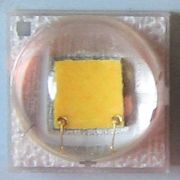 |
45 KB | Brted | a little brighter | 2 |
| 18:59, 8 March 2016 | Cree-xpl-hi.jpg (file) | 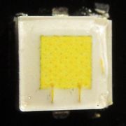 |
67 KB | Brted | 2 | |
| 20:06, 6 March 2016 | Nichia219c.jpg (file) | 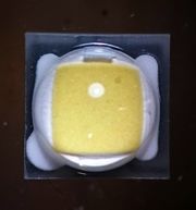 |
17 KB | Brted | rotated to put cathode at lower left like other pictures | 2 |
| 07:24, 25 February 2016 | A17l-fet+1.jpg (file) | 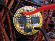 |
140 KB | Brted | A17L FET + 1 driver developed by Wight and used in the BLF A6. The microprocessor on the left controls the FET (on the right) and the 7135 (bottom) provides regulation for Low and Medium modes. | 1 |
| 12:00, 7 February 2016 | Xp-l.jpg (file) | 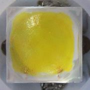 |
38 KB | Brted | 2 | |
| 20:42, 6 December 2015 | Flashlight-parts.jpg (file) | 109 KB | Brted | Exploded view of Supfire A6-T6 by BLF member djozz, annotated by BLF member KGB. Used with permission. | 1 | |
| 13:09, 28 February 2015 | Digichargerd4.jpg (file) | 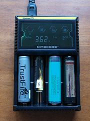 |
179 KB | Brted | Nitecore Digicharger D4 can charge 4 batteries of different sizes and chemistries including NiMH, Li-ion, IMR, and LiFePo4 and has a digital readout for voltage, current, time, and charging status. | 1 |
| 12:36, 1 February 2015 | Nichia219b.jpg (file) | 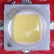 |
28 KB | Brted | Nichia 219b LED | 1 |
| 14:14, 4 May 2014 | Sunwaymand40a.jpg (file) | 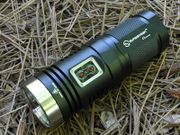 |
222 KB | Brted | Sunwayman D40A | 1 |
| 16:32, 29 September 2013 | Ultrafire-c8.jpg (file) | 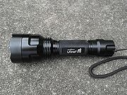 |
250 KB | Brted | UltraFire C8 is an 18650 light with a larger diameter head for greater throw. | 1 |
| 13:06, 4 July 2013 | Cree xr-e.jpg (file) | 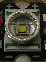 |
36 KB | Brted | Not worried about hotlinking anymore | 2 |
| 13:04, 4 July 2013 | Ansiwhite.jpg (file) | 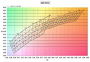 |
395 KB | Brted | Not worried about hotlinking anymore | 2 |
| 10:44, 2 July 2013 | Nanjg 105C. 600.jpg (file) | 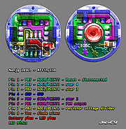 |
183 KB | JackCY | Updated layout under ATtiny13A based on another image reference. | 1 |
| 17:12, 29 June 2013 | Ansi-white.jpg (file) | 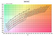 |
395 KB | Brted | Chromaticity chart with divisions used by Cree and Philips Lumiled with some subdivisions used only by Cree. This chart was generated by CPF user DFiorentino and is used at Flashlight Wiki by permission. | 1 |
| 12:54, 29 June 2013 | Cree xre.jpg (file) | 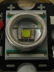 |
36 KB | Brted | Cree XR-E LED (from a Uniquefire S10). The brown outline around the die indicates this XR-E uses the smaller EZ900 die | 1 |
| 16:14, 24 June 2013 | DIY SOIC Clip.jpg (file) | 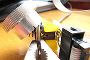 |
83 KB | JackCY | DIY SOIC Clip. | 1 |
| 16:06, 24 June 2013 | MHV AVR Tools and Atmel Studio 6.1 configuration in AVR Eclipse.png (file) | 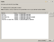 |
7 KB | JackCY | 1 | |
| 13:48, 6 April 2013 | Tail.jpg (file) | 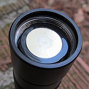 |
68 KB | Brted | End of flashlight with tail removed. To bypass the switch, use a wire or paper clip to connect the negative end of the battery to the bare metal threads on the tube. The light should light up. If you have an amp meter, you can measure tailcap current d... | 1 |
| 13:46, 6 April 2013 | Tailcap.jpg (file) | 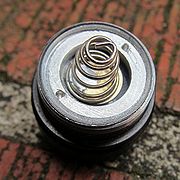 |
79 KB | Brted | Flashlight tailcap showing spring and retaining ring with dimples. Use needlenose pliers in the dimples to tighten the ring. This tailcap is from an Ultrafire WF-502B. | 1 |
| 16:04, 14 March 2013 | Cree-xte.jpg (file) | 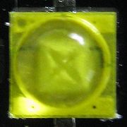 |
57 KB | Brted | rotate image 90 degrees to match other LED's on page | 2 |
| 15:06, 1 March 2013 | Coatedlens.jpg (file) | 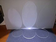 |
28 KB | Brted | The glass lens with anti-reflective coating on the right shows an obvious decrease in the amount of light reflected onto the wall vs. the uncoated plastic lens in the center and the uncoated glass lens on the left. Because of the sharp angle of light o... | 1 |
| 12:10, 3 February 2013 | Cree-xml.jpg (file) | 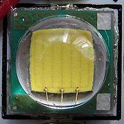 |
62 KB | Brted | Updated picture isn't as dark. The LED shown is a neutral XM-L from Illumination Supply | 2 |
| 12:08, 3 February 2013 | Creexm-l2.jpg (file) | 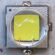 |
70 KB | Brted | The Cree XM-L2 LED is the same size as the original XM-L, but it is a new design. The top is silver, the strips are gone, and there are only 2 bonding wires instead of 3. The LED shown is a T6 flux bin with 3C tint bin from International Outdoor. | 1 |
| 21:47, 15 October 2012 | Luxeonc.jpg (file) | 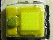 |
20 KB | Brted | Luxeon C LED, from a Maglite Solitaire LED flashlight | 1 |
| 18:37, 3 October 2012 | Creexb-d.jpg (file) | 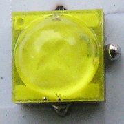 |
45 KB | Brted | Cree XB-D LED is similar to the XT-E, but smaller. | 1 |
| 19:05, 4 September 2012 | Xpg2.jpg (file) | 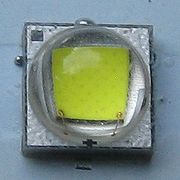 |
42 KB | Brted | Cree XP-G2 LED | 1 |
| 09:30, 7 June 2012 | Samsung3535.jpg (file) | 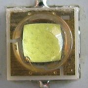 |
45 KB | Brted | Samsung 3535 LED from a Ultrafire P60 drop-in sold by Manafont. | 1 |
| 21:24, 29 May 2012 | Osram-oslon.jpg (file) | 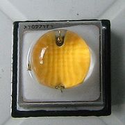 |
41 KB | Brted | Osram Oslon Square LED | 1 |
| 18:31, 27 May 2012 | Cree-xpc.jpg (file) | 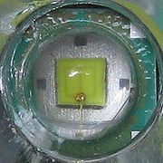 |
38 KB | Brted | Cree XP-C LED installed under the reflector of a Streamlight Microstream. | 1 |
| 18:59, 10 May 2012 | Nichia219.jpg (file) | 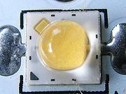 |
43 KB | Brted | Nichia 219 LED has the same footprint as a Cree XP-G | 1 |
| 16:34, 25 February 2012 | Fenix-l2d-p2d.jpg (file) | 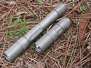 |
200 KB | Brted | Fenix L2D and P2D Premium Q5 with Cree XR-E Q5 LED, olive colored | 1 |
| 16:29, 25 February 2012 | Sunwayman-v10a.jpg (file) | 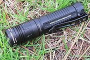 |
171 KB | Brted | Sunwayman V10A with Cree XP-G R5 | 1 |
| 09:28, 18 February 2012 | Baked-anodized-lights.jpg (file) | 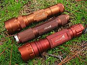 |
222 KB | Brted | Three lights that were originally black, after being broiled in an oven at 500 degrees F for 30 minutes. The resulting color varies from one manufacturer to another, with the biggest tint shifts available from Type II anodizing, which is more common on bu | 1 |
| 17:23, 11 February 2012 | Mobile-menu.png (file) | 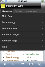 |
114 KB | Brted | Screenshot of the mobile version of the Flashlight Wiki showing the drop down menu. Taken on a iPod Touch 4G. | 1 |
| 17:22, 11 February 2012 | Mobile-home.png (file) | 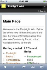 |
122 KB | Brted | Screenshot of the mobile version of the Flashlight Wiki home page, taken on an iPod Touch 4G. | 1 |
| 20:24, 30 November 2011 | Ledtints.jpg (file) | 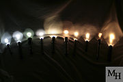 |
271 KB | Brted | From left to right (white balance set to 5,200K): Quark MiNi AA (cool white XP-G R5), Olight T20-M (XR-E Q5), Quark 123² Turbo (XP-G S2), 4Sevens Preon 2 (neutral XP-G R4), Quark RGB (neutral white MC-E), SureFire 6P (incandescent), 4Sevens Preon 2 ( | 1 |
| 14:28, 15 May 2011 | P60-disk.jpg (file) | 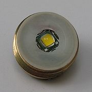 |
55 KB | Brted | Isolation disk placed over the top of the driver. This prevents the aluminum reflector causing a short between the positive and negative parts of the LED. This is a 18mm disk, but it is better to get a 16mm disk which fits inside the outer rim of the pill | 1 |
| 09:28, 15 May 2011 | P60-driverdry.jpg (file) | 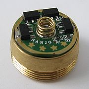 |
69 KB | Brted | square picture | 2 |
| 09:19, 15 May 2011 | P60-ledwired.jpg (file) | 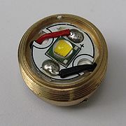 |
71 KB | Brted | The LED with leads from the driver soldered in place. Make sure the solder points don't stick up too high or they could interfere with the reflector. | 1 |
| 09:09, 15 May 2011 | P60-positive.jpg (file) | 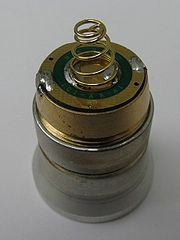 |
47 KB | Brted | The bottom of the driver board with the small spring for contact with the positive end of the battery and solder bridges from the driver board to the pill. | 1 |
| 22:14, 14 May 2011 | P60-leads.jpg (file) | 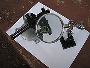 |
67 KB | Brted | Red and black leads are soldered to the driver board. It helps to hold the work in a vise (this is a PanaVise). A magnifying lens helps too (this is called a third hand). | 1 |
| 21:45, 14 May 2011 | P60-center.jpg (file) | 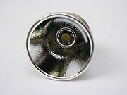 |
44 KB | Brted | Once the LED is in place, you can check whether it is centered by screwing the reflector over it. Before the adhesive sets up, you make adjustments to get the LED perfectly centered. | 1 |
| 21:40, 14 May 2011 | P60-ledmounted.jpg (file) | 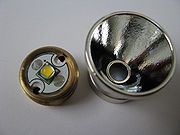 |
58 KB | Brted | The LED is glued to the top of the brass pill with thermal adhesive. The key is to get the LED centered and not to cover the holes where the leads from the driver will come up to attach to the LED later. | 1 |
| 21:25, 14 May 2011 | P60-parts.jpg (file) | 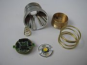 |
51 KB | Brted | Parts to build a P60 drop-in. The only things not shown here are an isolation disk and the lead wires from the driver to the LED. | 1 |
| 21:28, 17 April 2011 | Turnigy.jpg (file) | 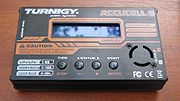 |
104 KB | Brted | Turnigy Accucell 6 hobby charger | 1 |
| 09:03, 9 April 2011 | Ribbon.jpg (file) | 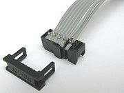 |
66 KB | Brted | The 8-wire ribbon from the clip must be modified to connect to Pin 9 of the USB ISP programmer. Open up the end of the ribbon and move wire 8 over to the 9th position then reassemble. | 1 |
| 08:48, 9 April 2011 | Usbisp.jpg (file) |  |
52 KB | Brted | USB ISP AVR programming board. This attaches to the computer and the ribbon from the clip attaches to this board. | 1 |
| 08:40, 9 April 2011 | Soic8clip.jpg (file) | 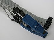 |
74 KB | Brted | An SOIC 8 clip with ribbon cable attached. The individual wires of the ribbon must be re-ordered to attach to the correct pins of the Atmel chip the clip will attach to. The 8-wire ribbon has a 10-wire plug that attaches to the USB ISP programmer. | 1 |
| 08:37, 9 April 2011 | Avrisp.jpg (file) | 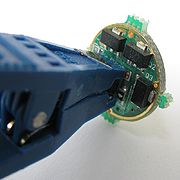 |
95 KB | Brted | An SOIC 8 clip attached to an Atmel Tiny13A chip on a flashlight driver board. This is the NANJG AK-47 driver. | 1 |
| 17:03, 8 April 2011 | Ak47pins.jpg (file) | 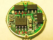 |
128 KB | Brted | Picture of NANJG AK-47 driver with ATMEL ATTiny13 pin numbers labelled. | 1 |