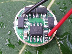
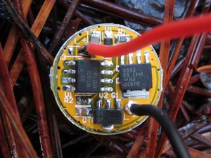
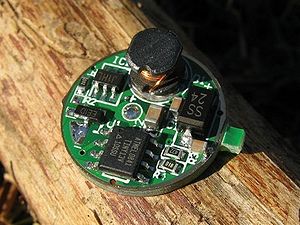
Driver
The driver consists of the electronics that take power from the battery and send power to the LED. They amplify or reduce the voltage from the batteries to the correct level for the LED and also control the amount of current that can be delivered. The driver also contains the electronics that give the flashlight its user interface, including the number of modes and how those work relative to button presses. The driver has a positive and negative input from the battery, and a positive and negative output that goes to the LED.
Power Regulation
Only by correctly combining the power supply, driver, and LED will a LED function properly. Many Cree LEDs require 3.3 volts to light up. If a flashlight is powered by a single AA battery, then the voltage must be amplified. However if a light uses 2 3-volt CR123 batteries with 6 volts, the voltage must be reduced. Power regulation supplies a constant voltage to the LED so that the brightness of the flashlight is constant for most its period of use (many circuits stop working once the battery gets low and brightness will slowly fall off, which is better than the light just turning itself off without warning).
Direct Drive

If you apply the correct voltage, you don't need a driver at all. Lithium-ion batteries conveniently provide a decent voltage without any further modification. This is quite efficient since all of the power from the battery is delivered to the LED. However a fresh li-ion battery starts at 4.2 volts fully charged and will be 3.6 volts when it needs to be recharged. As power is applied to the LED, it will draw a certain amount of current from the battery. This current increases with the voltage. When the voltage is higher, the LED will be very bright and draw a great deal of current. As voltage decreases the light will dim and draw less current. If a constant brightness is desired, a driver that offers some kind of regulation is required. Also, many LEDs are being overdriven by 4.2 volts of a fresh li-ion battery.
Linear Regulator
Though people call this type of driver a linear regulator, linear regulators regulate the voltage. However these drivers have a number of AMC7135 current regulating chips installed. Each chip allows 350mA of current through and when wired in parallel, the current adds, so 700mA from 2 chips, 1050mA from 3 chips, and 1400mA from 4 (some drivers have higher binned regulator chips that allow 380mA through). Eight 350mA chips (using two boards or both sides of one 17mm board) gives 2800mA which is ideal for XM-L2 and XP-L LEDs. Constrained to a particular current, the LED will settle in at its Vf for that current and the rest of the voltage from the battery will be converted to heat by the regulator chips. Because any voltage beyond the required amount is wasted as heat, supplying a higher voltage is less efficient and the board becomes more efficient as the input voltage approaches the output voltage. As the voltage supplied drops below the Vf of the LED plus some overhead for the chips, the driver drops out of regulation and goes into direct drive and the light will start to dim. These drivers can also have modes by using a microcontroller utilizing PWM for lower modes and flashing modes.
FET Driver

This driver uses a field effect transistor (FET or MOSFET) in combination with a microprocessor to control current to the LED. The FET is basically a switch with very low resistance (lower than running the full current through the microprocessor) and can be turned on and off by the microprocessor using PWM. Without PWM, it is basically like running the light on direct drive so there is no protection of the LED. Some FET drivers add a linear regulator 7135 so the need for PWM on lower modes is reduced. This multichannel approach lets the driver limit the current to 350mA (instead of unlimited through the FET) and use PWM as needed to work from there. Also the 350mA channel gives more uniform low levels whereas the levels from the FET vary with battery strength.
Boost Circuit

Modifying the voltage of a DC power supply is described by Wikipedia in the DC to DC converter article. Increasing the voltage is done by a boost converter circuit, also called a step-up circuit. The efficiency of a boost converter increases as the voltage supplied gets closer to the output voltage. For instance a flashlight that uses one 1.2V NiMH cell will not be as efficient as one that uses two, since in one case the boost converter is nearly tripling the voltage and in the other is not even doubling it. This is why a flashlight can work using either one or two batteries but will be brighter with two. If the source voltage exceeds the target voltage, some drivers will go into direct drive and some will just burn out. Therefore it is important to match up the driver's voltage range with the batteries you will be using.
Buck Circuit
A buck circuit is similar to the boost circuit above, but in reverse. It takes a higher voltage and reduces it down to the voltage desired. This is used in flashlights with multiple cells in series, for instance when there are two 3V CR123 batteries (or 2 3.7V 16340 li-ion batteries). The buck circuit is also quite efficient, but typically requires at least a 0.5V reduction to operate and therefore not as appropriate when using a single li-ion cell.
Buck-Boost Circuit
The Buck/Boost Converter provides the greatest flexibility in input voltage and will boost or buck the voltage as appropriate. Good luck finding one at a reasonable price though.
Other Driver Features
In addition to regulating the voltage, the driver controls brightness levels and how the user switches between those by monitoring button clicks and presses. Therefore some drivers offer various modes and some do not. Some offer different packages of modes that are available either by the user pressing buttons or they can be hard wired by soldering bridges on the driver board.
The size of the driver itself is also important. The most common size is 17mm which works well in most P60 drop-ins and many lights powered by an 18650 li-ion battery. However, smaller lights uses smaller diameter boards that are harder to find. There are also larger circuit boards of around 25mm used on larger flashlights.
More Information
See Popular drivers for some specific drivers available.
Very informative post on CPF with pictures and graphs.