File list
Jump to navigation
Jump to search
This special page shows all uploaded files.
| Date | Name | Thumbnail | Size | User | Description | Versions |
|---|---|---|---|---|---|---|
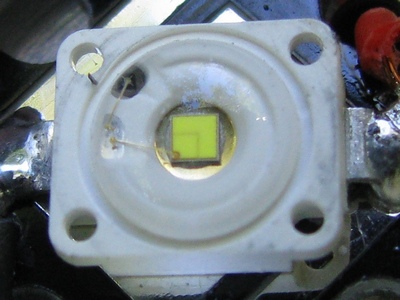
| 00:15, 28 November 2010 | Osram-led.jpg (file) |  |
60 KB | Brted | Osram LED from a UniqueFire AA-S1 flashlight | 1 |
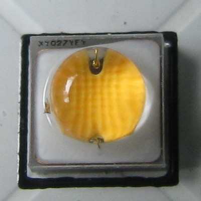
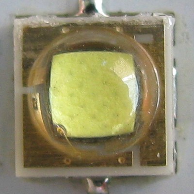
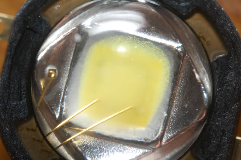
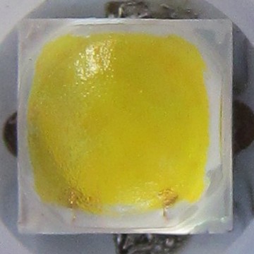
| 21:24, 29 May 2012 | Osram-oslon.jpg (file) |  |
41 KB | Brted | Osram Oslon Square LED | 1 |
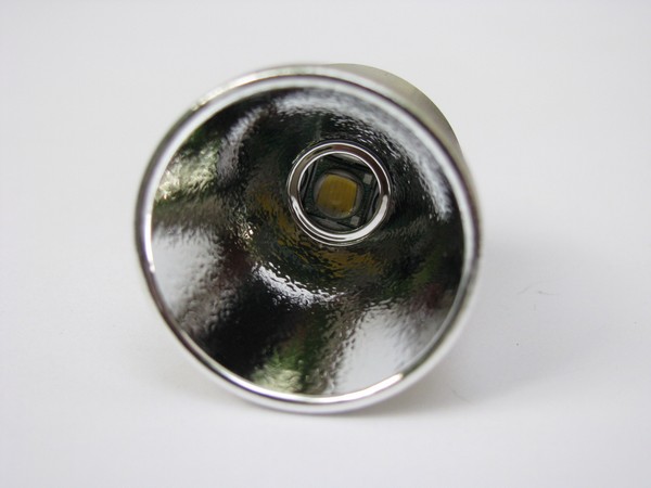
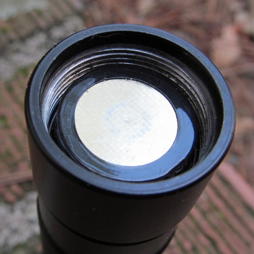
| 21:45, 14 May 2011 | P60-center.jpg (file) |  |
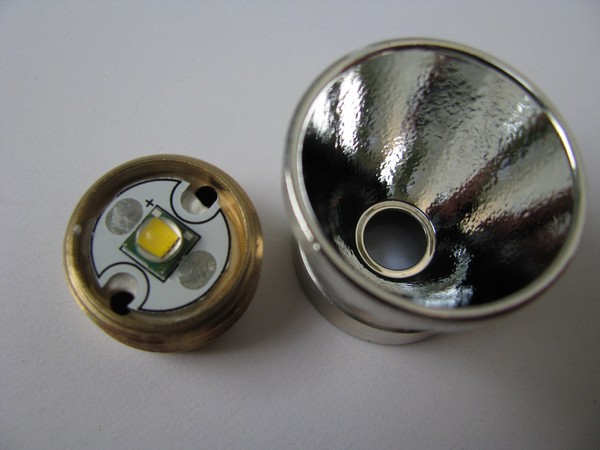
44 KB | Brted | Once the LED is in place, you can check whether it is centered by screwing the reflector over it. Before the adhesive sets up, you make adjustments to get the LED perfectly centered. | 1 |
| 14:28, 15 May 2011 | P60-disk.jpg (file) |  |
55 KB | Brted | Isolation disk placed over the top of the driver. This prevents the aluminum reflector causing a short between the positive and negative parts of the LED. This is a 18mm disk, but it is better to get a 16mm disk which fits inside the outer rim of the pill | 1 |
| 09:28, 15 May 2011 | P60-driverdry.jpg (file) |  |
69 KB | Brted | square picture | 2 |
| 22:14, 14 May 2011 | P60-leads.jpg (file) |  |
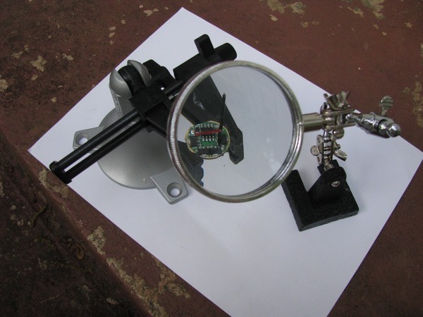
67 KB | Brted | Red and black leads are soldered to the driver board. It helps to hold the work in a vise (this is a PanaVise). A magnifying lens helps too (this is called a third hand). | 1 |
| 21:40, 14 May 2011 | P60-ledmounted.jpg (file) |  |
58 KB | Brted | The LED is glued to the top of the brass pill with thermal adhesive. The key is to get the LED centered and not to cover the holes where the leads from the driver will come up to attach to the LED later. | 1 |
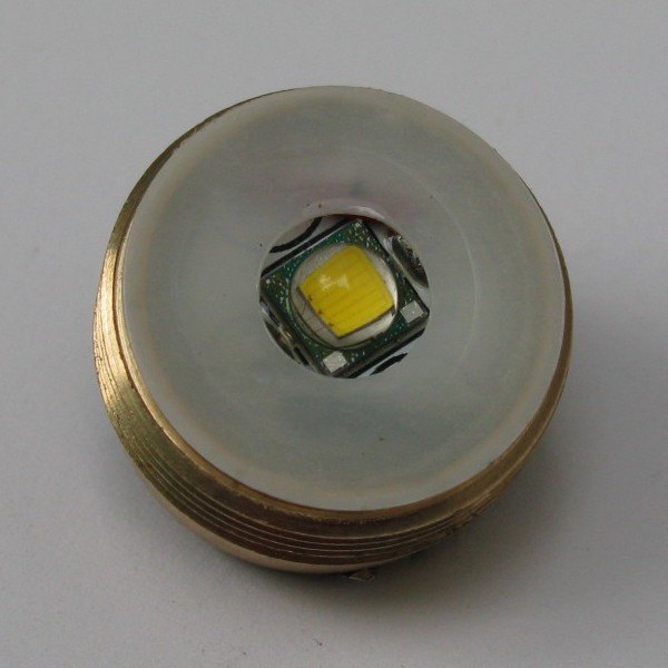
| 09:19, 15 May 2011 | P60-ledwired.jpg (file) |  |
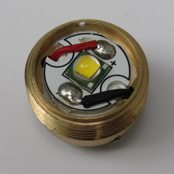
71 KB | Brted | The LED with leads from the driver soldered in place. Make sure the solder points don't stick up too high or they could interfere with the reflector. | 1 |
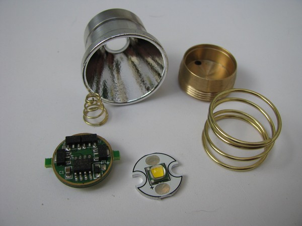
| 21:25, 14 May 2011 | P60-parts.jpg (file) |  |
51 KB | Brted | Parts to build a P60 drop-in. The only things not shown here are an isolation disk and the lead wires from the driver to the LED. | 1 |
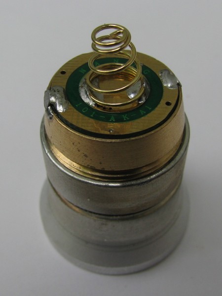
| 09:09, 15 May 2011 | P60-positive.jpg (file) |  |
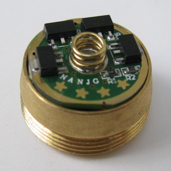
47 KB | Brted | The bottom of the driver board with the small spring for contact with the positive end of the battery and solder bridges from the driver board to the pill. | 1 |
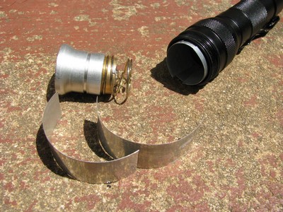
| 19:54, 28 November 2010 | P60dropin-and-strips.jpg (file) |  |
64 KB | Brted | A P60 drop-in and UltraFire WF 502B host with aluminum strips cut from a soda can to provide better heatsinking for the drop-in. | 1 |
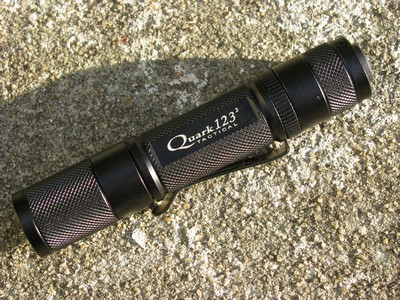
| 20:12, 28 November 2010 | Quark-123-2.jpg (file) |  |
81 KB | Brted | Quark 123-2 Tactical flashlight by 4Sevens | 1 |
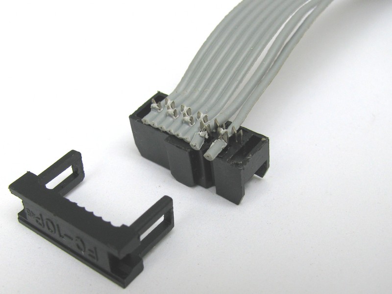
| 09:03, 9 April 2011 | Ribbon.jpg (file) |  |
66 KB | Brted | The 8-wire ribbon from the clip must be modified to connect to Pin 9 of the USB ISP programmer. Open up the end of the ribbon and move wire 8 over to the 9th position then reassemble. | 1 |
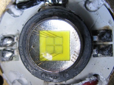
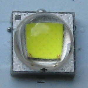
| 09:30, 7 June 2012 | Samsung3535.jpg (file) |  |
45 KB | Brted | Samsung 3535 LED from a Ultrafire P60 drop-in sold by Manafont. | 1 |
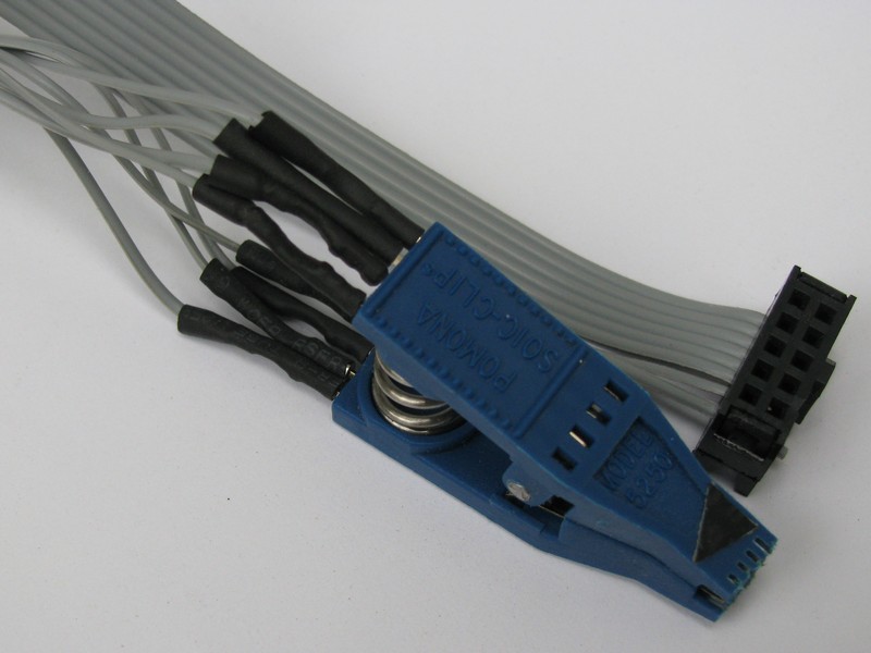
| 08:40, 9 April 2011 | Soic8clip.jpg (file) |  |
74 KB | Brted | An SOIC 8 clip with ribbon cable attached. The individual wires of the ribbon must be re-ordered to attach to the correct pins of the Atmel chip the clip will attach to. The 8-wire ribbon has a 10-wire plug that attaches to the USB ISP programmer. | 1 |
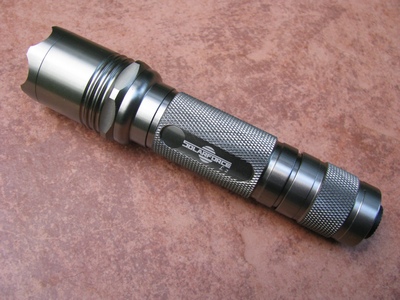
| 21:30, 28 November 2010 | Solarforcel2.jpg (file) |  |
69 KB | Brted | Solarforce L2 in gunmetal gray | 1 |
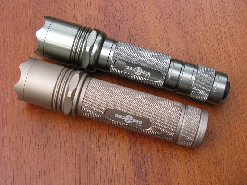
| 11:25, 11 December 2010 | Solarforcex2.jpg (file) |  |
155 KB | Brted | Solarforce L2 (gunmetal gray) and L2i (sand). | 1 |
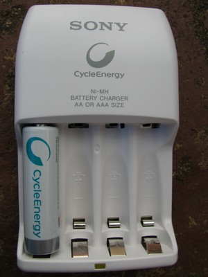
| 22:39, 26 February 2011 | Sony-bcg34hld.jpg (file) |  |
32 KB | Brted | Sony BCG-34HLD charger with Sony Cycle Energy 1000mA LSD battery | 1 |
| 09:21, 18 January 2011 | Sscp4.jpg (file) |  |
90 KB | Brted | Seoul Semiconductor P4 LED, U bin. Photo by Peter Cheuk, used with permission. | 1 |
| 20:54, 28 November 2010 | Sscp7led.jpg (file) |  |
47 KB | Brted | Seoul Semiconductor P7 LED | 1 |
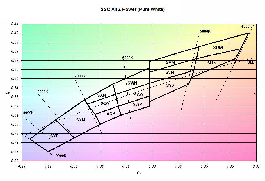
| 14:23, 31 December 2010 | Ssctints.jpg (file) |  |
89 KB | Brted | Previous version was not for P4 and P7 LED's. This one is. | 2 |
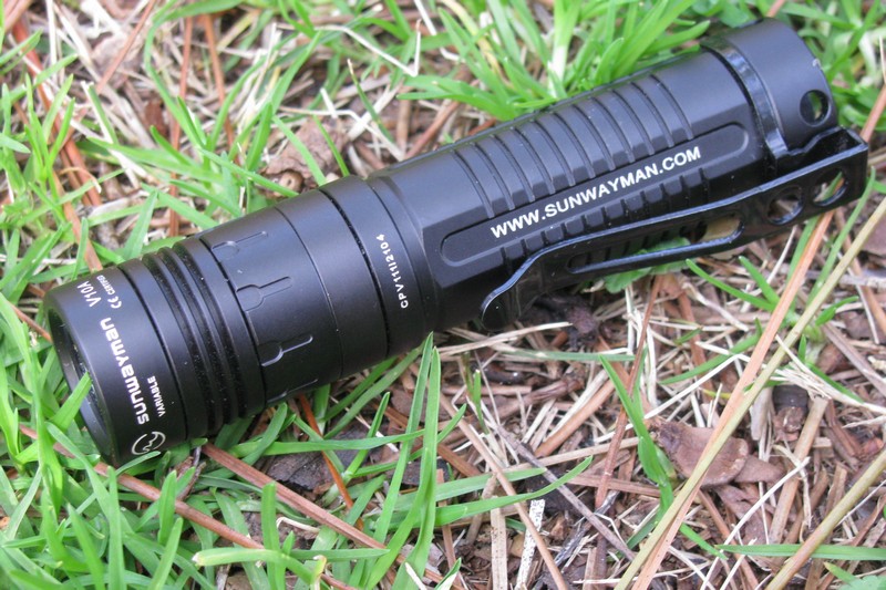
| 16:29, 25 February 2012 | Sunwayman-v10a.jpg (file) |  |
171 KB | Brted | Sunwayman V10A with Cree XP-G R5 | 1 |
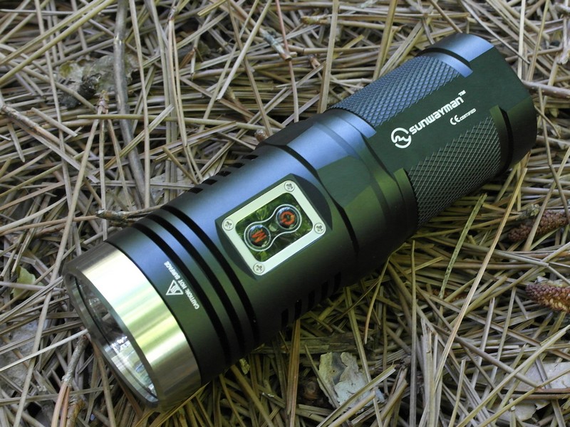
| 14:14, 4 May 2014 | Sunwaymand40a.jpg (file) |  |
222 KB | Brted | Sunwayman D40A | 1 |
| 13:48, 6 April 2013 | Tail.jpg (file) |  |
68 KB | Brted | End of flashlight with tail removed. To bypass the switch, use a wire or paper clip to connect the negative end of the battery to the bare metal threads on the tube. The light should light up. If you have an amp meter, you can measure tailcap current d... | 1 |
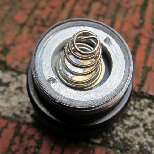
| 13:46, 6 April 2013 | Tailcap.jpg (file) |  |
79 KB | Brted | Flashlight tailcap showing spring and retaining ring with dimples. Use needlenose pliers in the dimples to tighten the ring. This tailcap is from an Ultrafire WF-502B. | 1 |
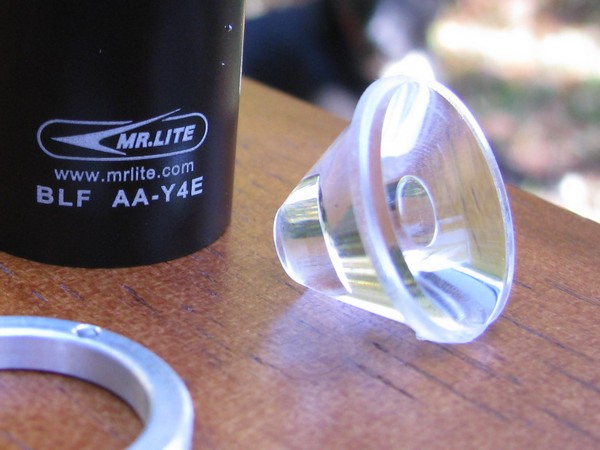
| 21:56, 6 March 2011 | Tir-optic.jpg (file) |  |
66 KB | Brted | Total internal reflection optic. This lens is made of plastic and came with the Mr.Lite BLF-Y4E, which has a Cree XR-E Q5 LED. | 1 |
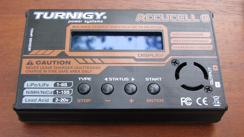
| 21:28, 17 April 2011 | Turnigy.jpg (file) |  |
104 KB | Brted | Turnigy Accucell 6 hobby charger | 1 |
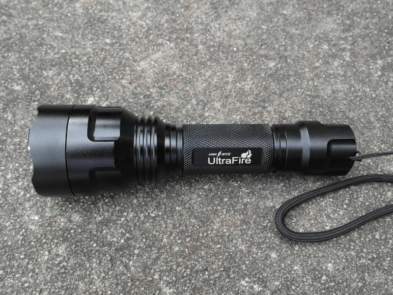
| 16:32, 29 September 2013 | Ultrafire-c8.jpg (file) |  |
250 KB | Brted | UltraFire C8 is an 18650 light with a larger diameter head for greater throw. | 1 |
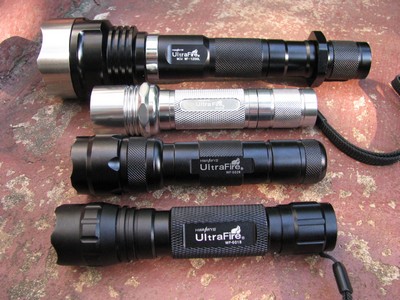
| 22:00, 28 November 2010 | Ultrafires.jpg (file) |  |
55 KB | Brted | From the top: UltraFire models MCU WF-1200L, WF-504B, WF-502B, and WF-501B | 1 |
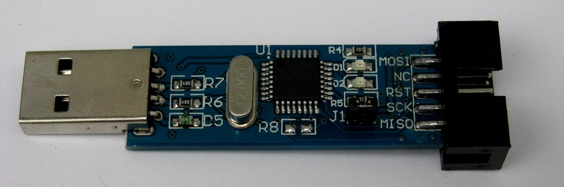
| 08:48, 9 April 2011 | Usbisp.jpg (file) |  |
52 KB | Brted | USB ISP AVR programming board. This attaches to the computer and the ribbon from the clip attaches to this board. | 1 |
| 12:00, 7 February 2016 | Xp-l.jpg (file) |  |
38 KB | Brted | 2 | |
| 19:05, 4 September 2012 | Xpg2.jpg (file) |  |
42 KB | Brted | Cree XP-G2 LED | 1 |